Selection of the proper Cable Bus system must be under taken with care to assure that it compliments the design of the overall electrical power system.
Cable Bus
Electrical Design
To ensure an efficient, dependable, high quality installation, MP Husky Cable Bus System can be fully engineered with particular emphasis placed on cables, system balance, short circuit capability, and ground requirements. Each one of these key design considerations must be analyzed separately to determine how they affect the overall system design.
Cable Bus
Parallel Conductors
Parallel conductors (more than one per phase) can be used to an advantage in Cable Bus where large conductor sizes are encountered. The ampacity per circular mil of conductor decreases as the circular mil or conductor increases. Smaller conductors running parallel are more flexible during installation and have greater current carrying capability than fewer, larger conductors.
Cable Bus
Voltage Drop
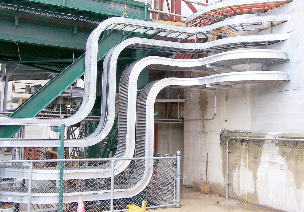
Proper system design dictates that voltage drop be considered for both the power feeders separately as well as the entire power system. A voltage drop of 3-4% for power feeders and an overall of 5% or less for the entire system are considered to be within acceptable limits. Cable Bus is designed for low-voltage drop. Voltage drop data is available upon request, for your specific system.
Cable Bus
System Balance
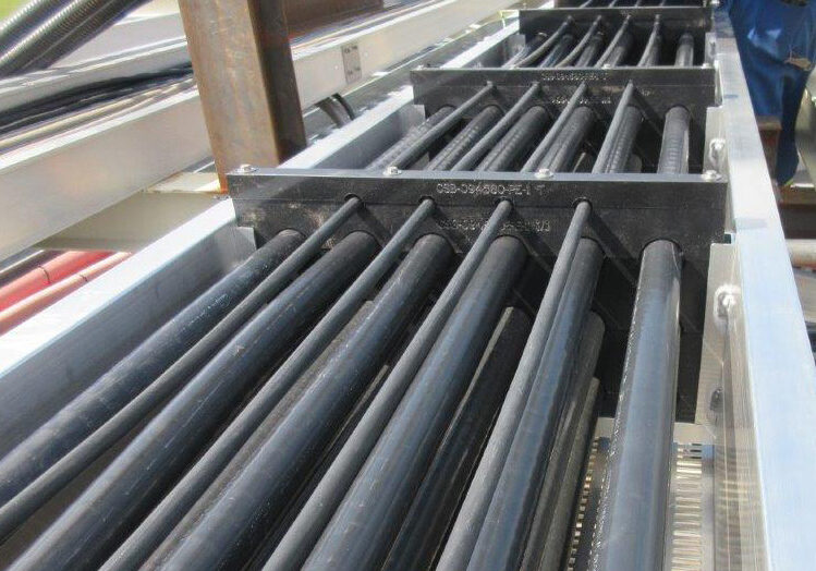
Cable Bus is power distribution system using insulated conductor power cables with support blocks that maintain cable spacing. Each phase consists of one or more cables connected in parallel. The complete assembly is enclosed in a ventilated aluminum enclosure for support and protection.
Parallel conductor transmission lines, using widely spaced conductors have been in use for many years. The electrical coupling between the conductors of a parallel conductor system, which is a function of the geometry of the location of the conductors, can cause an imbalance in the conductor currents. In a widely spaced overhead transmission line transposition of conductors can economically be used to balance the conductor currents.
The spacing of the conductors in Cable Bus is one cable diameter, (i.e. one to three inches), as compared to the typical value of thirty feet used in overhead lines. This close spacing and the relatively short lengths, as compared to hundreds of miles for overhead lines, make the transposition of conductors within the bus housing a difficult challenge and sometimes practically impossible.
The objective of the Cable Bus design is to obtain the optimum balance for an electrical circuit using parallel conductors (no transposition) with close spacing. MP Husky has developed an Inductive Reactance Program which solves for the line and phase currents of a parallel conductor system using a mathematical model of the transmission line parameters. Through the use of computer programs and verification by laboratory and field testing, MP Husky has designed Cable Bus Systems with minimal imbalance.
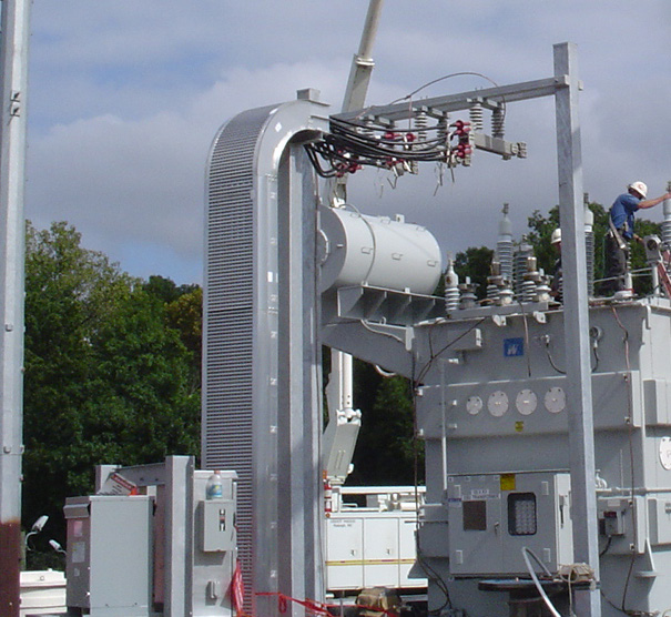
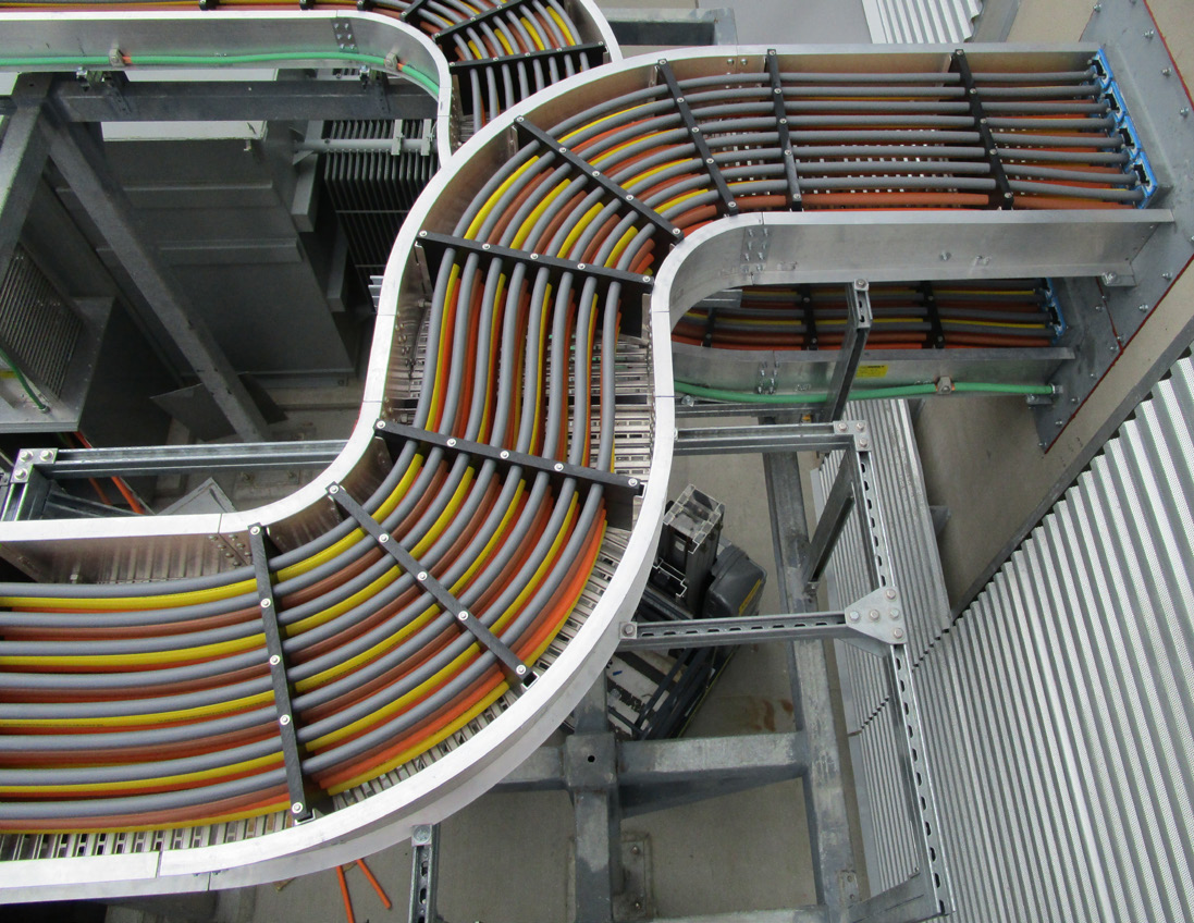
MP Husky Cable Bus is designed for balance of conductors within a phase (intra-phase) and balance between the phases (inter-phase). Many phasing arrangements will provide inter-phase balance of currents due to the load impedance, but the majority of these phasing arrangements provide intra-phase current imbalance.
MP Husky’s Cable Bus design provides a phasing arrangement that achieves inter-phase current balance, as well as intra-phase current balance, therefore reducing the amount of parallel conductor imbalance to a minimum.
Cable Bus
Short Circuit Testing
The Cable Bus systems were tested on a 600 volt, 3 phase, 60Hz circuit having a power factor of less than 0.20. One end of the Cable Bus was connected to the source terminals and the other was short circuited to create a three phase bolted fault.
Each test was conducted for a minimum of six cycles.
Oscillograms recorded the phase currents during the test. Still photographs and high speed color motion pictures were taken relevant to the test.
MP Husky Cable bus has been subjected to currents of 39,000, 67,500, 85,000, 100,000, 120,000, 125,000, 150,000, 175,000, and 200,000 RMS symmetrical amperes with asymmetrical currents greater than 200,000 amperes. Cable Bus withstood the mechanical forces of the test without any damage to the cables, support blocks or enclosure.
Cable Bus
Shielding
Shielding is used on power cables to confine the dielectric field of the conductor to the cable insulation. Shielded Power Cables are used in Cable Bus for applications above 2500 volts and when any of the following conditions exist:
- Where cables are subject to soot or other heavy deposits that may form paths to ground.
- Where electrostatic discharge can effect nearby computerized control cables or other low level signals.
- Concern for personal safety.
When installing shielded cable the metallic shielding must be solidly grounded and the installation must be studied to determine the best grounding method. This is necessary as voltage is induced in the shield of a single conductor cable carrying alternating current due to mutual inductance between its shield and any other conductor in its vicinity. This induced voltage can result in two conditions:
- Metal shield bonded or grounded at multiple points creates shield to ground circulating currents. The magnitude of the circulating currents depends on the mutual inductance to the other cables, the current in these conductors, and the resistance of the shield.
- Shields bonded or grounded at only one point will have a voltage build up in the sheath but will eliminate circulating currents.
The length of the circuit and the load conditions will indicate which of the above shielding methods is required for any particular reason. MP Husky’s engineers can provide shield voltage calculations to aid the client in choosing the best grounding method.
Cable Bus
Short Circuit Capacity
A Cable Bus system must be able to withstand the dangerous mechanical forces created by short circuit currents. These forces are transmitted from the conductors to the cable supports. In the case of Cable Bus, the support elements include the support blocks and enclosure.
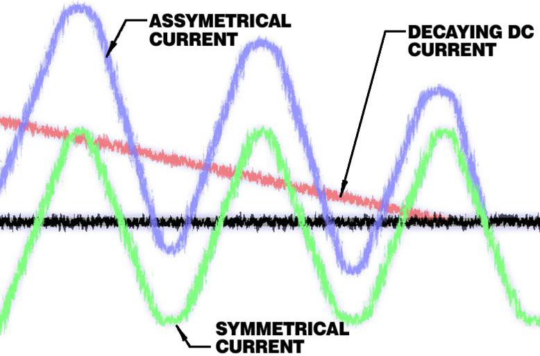
Short circuit currents are made up of two parts; a symmetrical AC component and a rapidly decreasing DC component, A Cable Bus system must be selected so that its mechanical strength will withstand the maximum instantaneous current and to a lesser degree the 5-8 cycle resultant symmetrical current. The symmetrical current is the actual value that a high voltage breaker will interrupt.
Since Cable Bus is often used for main feeder connections, (e.g. substation, generator or transformer to switchgear, load centers and high voltage machines), the available short circuit current will be that of the utility or generator supply through the transformers. In some cases the Cable Bus feeds large motors and the motor contribution to short circuit must also be considered. Numerous tables are available listing motor contributions for various operating conditions.
Available fault currents can be limited to some extent by conductor impedance. The impedance can be in the form of either conductor length, size or a combination of both.
The MP Husky Cable Bus design ignores these added conductor impedance; instead the worst fault conditions are always assumed. For design consideration a three phase short circuit current will result in the maximum mechanical forces for design considerations.
If Cable Bus is fed directly from the utility company service then short circuit current data will be available from the utility.
Where motor contributions are considered, the fault current due to the motor feedback will be a function of the voltage and is usually expressed as multiples of the motor full load current. NEMA standards are available which list these factors. Certified tests have been conducted to determine the short circuit performance of Cable Bus using various supporting arrangements.
Cable Bus
Grounding
A Cable Bus system must afford protection to life and property against faults caused by electrical disturbances. Lightning, electrical system failures, as well as failures in the system connected equipment all constitute possible fault hazard locations.
For this reason, all metal enclosures of the system, as well as non-current carrying or neutral conductors should be tied together and reduced to a common potential. This includes the structural steal of the building, water, steam and gas piping.
There are two distinct divisions to the system and equipment grounding problem. The system ground is the connection of the distribution system to earth by means of a neutral or grounded conductor and system grounding serves to limit the voltage, which might appear on the circuit due to lightning or accidental contact.
Cable Bus systems should be grounded to the substation structure and thus to the substation ground grid and to the building steel by means of the Cable Bus support materials. Cable Bus should also be grounded to the equipment or switchgear enclosure.
It is an accepted fact that ground currents tend to concentrate near power conductors and that cable enclosures take a large portion of the ground currents; therefore, it is important to consider Cable Bus as a major carrier of ground currents.
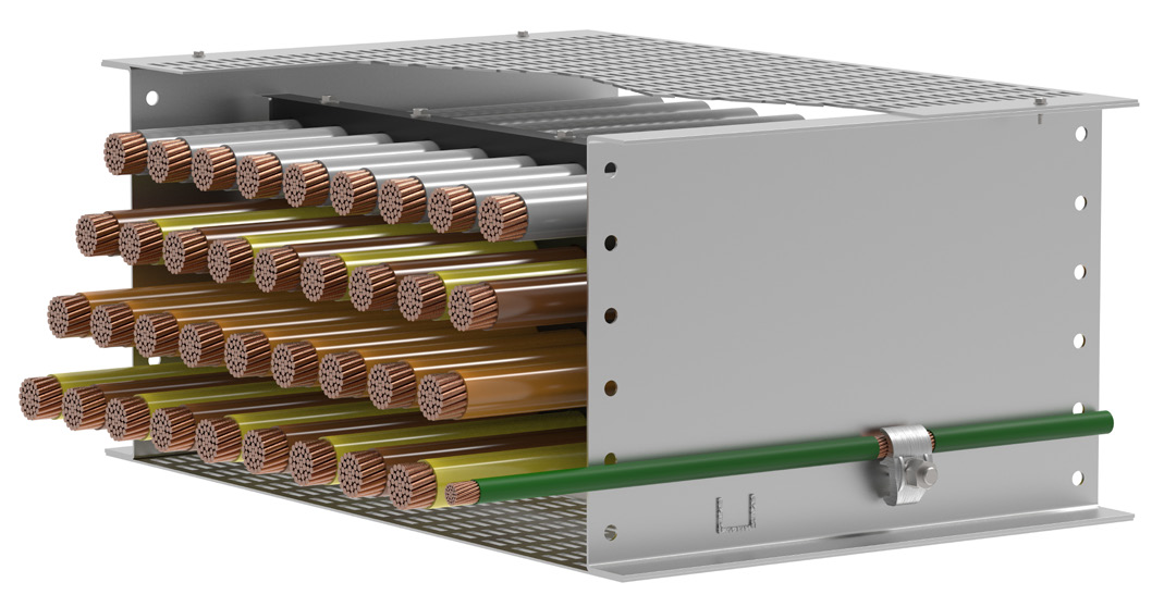
MP Husky’s Cable Bus enclosure is rated to carry 2000A ground current. Extra ground current capacity can be provided by the application of external ground conductors bonded to each section of Cable Bus housing.
Cable Bus
Flexibility
MP Husky Cable bus systems are flexible and adaptable to the many unexpected circumstances that occur during construction. Every size and rating of Cable Bus provided is supplied with up to 5% extra cable as well as one spare length of housing including cover, cable support blocks and hardware. This enables the installer to adjust our system in the field to unexpected changes or field obstructions with little or no delay of the project. And our compact design and radius bends allow our system to maneuver around and fit in tight clearance applications.
